Building the Essex from Takajian's plans
The Essex is a good subject for a ship model, as excellent plans for her exist - one of the benefits of being captured by the British. (see below) At the time Essex was built, most ship yards did not work from detailed plans or keep detailed records of materials used in building any particular ship or details of the design of the ship.
There were methods of diagramming a ship's hull, and in the case of Essex, a plan does exist, attributed to William Hackett, a prominent ship designer of the time. Such plans as there were, consisted of an excellent system of drawing the hull which specified the shape in three dimensions by showing cross sectional shapes at specified intervals, starting at the largest/widest portion of the hull, plus horizontal longitudinal sections also at specified intervals, and a detailed side view of the hull, which specified size and location of frame-members, location of masts, and certain other details. Because the horizontal section locations were also shown on the cross section profiles, and on the side profile, the system was keyed together and clearly defined the three dimensional shape of the hull. This plan or draft is often referred to as a ship's "lines".
When a ship was built, however, the lines of the hull on the plan were first used to build a scale model of the hull, then the scale model was used to make larger templates in a process called "lofting". The shipwrights then used the larger templates to make up the frames for the hull, defining its final shape. The process had plenty of opportunity for variation from the original design as conceived by the ship designer. The variation could happen from error in transferring the design from one form to another - paper plan to solid model to working template - and also because the people working the processes often had ideas of their own about what a ship should look like and might modify the shape to better fit their judgement about how the vessel should look.
In many cases, particularly with privately commissioned merchant vessels, a buyer simply approached a ship yard and ordered a vessel "like" one the yard had previously built, one that had performed well or otherwise had a good reputation. The buyer might want the new ship "bigger", or "sharper" or with some feature(s) to be added, but many shipyards depended on the skills and knowledge of the lofters and the ship wrights to build and in some cases to design the ship.
Upon the formation of a United States Navy, with the Naval Act of 1794, things got more formal pretty rapidly, with the design of the first frigates authorized by that Act standardized to a design by Joshua Humphreys. The Essex, however, was built outside the Naval contract process, as a private venture, so records are a bit scanty.
During the late 16th century through the mid 20th century, the British Royal Navy compensated and rewarded the crews of its ships through "prize money" after capture of an enemy vessel, whether it was a warship, a privateer, or a merchant vessel. When a Navy ship took a "prize", the vessel captured was evaluated through a very formal process involving an Admiralty Prize Court. If a merchant vessel was captured, the evaluation included the vessel and the cargo. For a war ship, the evaluation was based on a "fair price" for the ship if it were repairable and might be acceptable to be purchased by the Admiralty, and also included payments for each enemy sailor captured or killed. The prize money was divided among the officers and crew of all vessels participating in the capture and could be considerable, often more than a year's earnings for ordinary seamen and a fortune for the officers.
The evaluation process included a detailed "survey" of the vessel, including "taking off the lines" and an inventory of the structure of the ship, types of wood, details of construction, and so forth, as well as detailed drawings of equipment and ornamentation. These "admiralty plans" of prizes are maintained to this day by the British Navy and are an excellent source of plans of captured ships, particulary American ships of the Revolution and the War of 1812. In fact, these are probably the only good source of plans for early American ships. So the capture of the Essex resulted in excellent plans for today's modeler.
Portia Takakjian (1930-1992)
Portia Takakjian was a well known ship model builder who lived most of her life in upstate New York. Her initial training was in art, and in her early careers she worked as a fashion model and children's book illustrator and a draftsperson. She became interested in ship modeling through her sons.
Ms. Takakjian was known for the high quality of her models and her research. She published numerous articles on naval history and architecture and on ship modeling in Model Ship Builder magazine. Her book on the USF Essex, part of the "Anatomy of the Ship" series from Conway press was published posthumously in 2005. It is a remarkable book, perhaps the best of the series on 18th century sailing warships. The author thoroughly researched the plans for the ship and presents details of the construction of the hull and furnishings in remarkably fine drawings. She was working on a second book for the series, on the Raleigh (1778), at the time of her death.
The plans and the book by Takakjian are the basis for my model of the Essex.
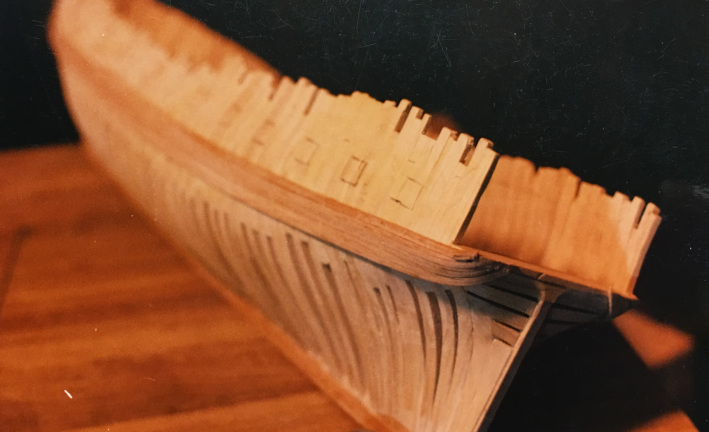
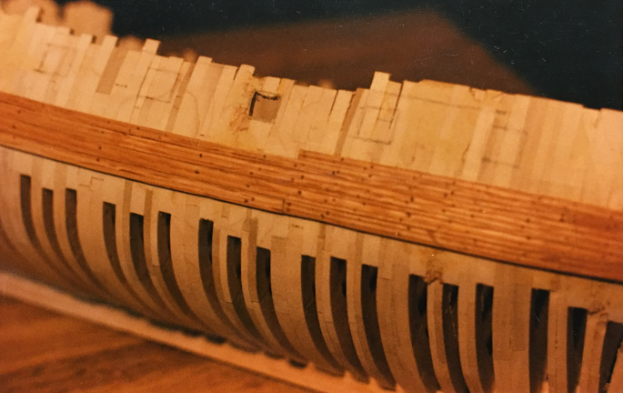
I built the model using oak for keel, stem and stern posts, and poplar for the frames. Takakjian had used double frames at intervals and I did the same, as shown in her plan. If doing the model again, I would not use poplar, but rather hard maple, as it is stronger and works better than poplar, and I would not double the frames, but go with a more traditional "make and space". I constructed the hull in the traditional way, setting up the keel, stem and stern posts, on a building board, then erecting the straight frams on the keel, using a sliding support to keep the frames square and plumb. Then I added the cant frames fore and aft, and filled in with hawse timbers, transoms, and deadwood. You can see an example of the sort of building jig I use for this method in the discussion of shop methods on the Ship Modeling Page. As mentioned elsewhere, I now much prefer building by the "Hahn method". See information on the model of the USF Raleigh for more information on that way of framing and planking a hull.
I planked the hull with red oak. In this case, I planked one side (starboard) fully, but left the other side planked only from the wales up to show the frames. I am aware that oak is a wood most model builders advise against using for ship models, but I mill the wood myself so I can pick and choose the boards to use and select them carefully when milling for planks. Admittedly, there is a lot of waste wood but I find the oak works well for keel, stem and stern posts, planking and some trim. The reason I first used the oak and maple for models was that both woods grew on our farm and could be harvested there. So I had an inexpensive source of both varieties, and a supply that has lasted until 2019, so far.
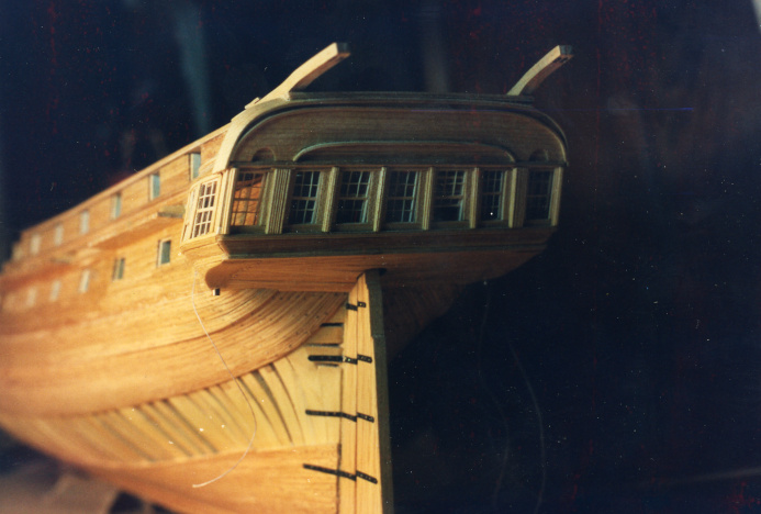
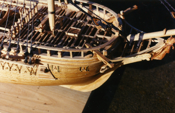
Once the frames were set up and faired inside and out, I planked the outside, starting with the wales on both sides, then the garboards. I planked one side (starboard) completely, and the other side incompletely, leaving a broad stretch unplanked. As mentioned below, I had intended to completely furnish the interior at first, but decided against it, for reasons given. Here are some shots of the planking of the hull. The nice "tuck" of the wales and adjacent planks at the stern/wing transoms is particularly attractive. At least to a ship modeler.
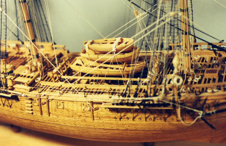
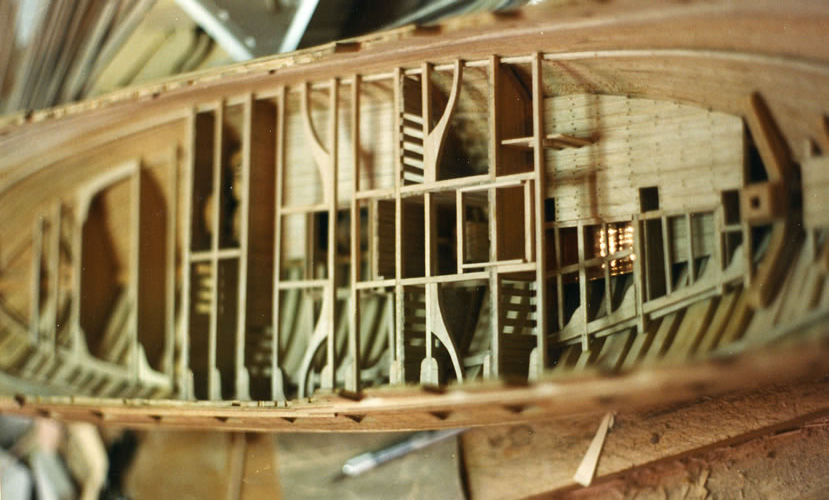
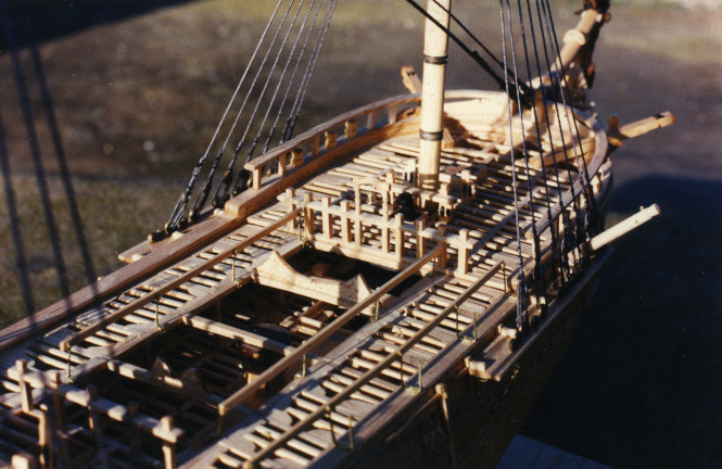
In the pictures below, you can see the after part of the planked orlop deck, the slatted partitions in the holds, and the well. If you look toward the stern, you can see the copper lining of the magazine and the elevated footing for the mizzen mast. You can also see the ceiling is installed on one side, and the clamps are in place for the berth deck and the gun deck. I have started placing the main beams of the berth deck amidships and the carlings around the hatches and companionways. Also the lovely curved members/knees beside the hatches. Once all the beams and carlings are in, I will add the purlins, building in any bitts, pumps, ladders, and so forth before planking half of that deck. In this model, I also built a rudder quadrant for the steering gear, but that ended up largely hidden beneath the deck planking of the next deck.
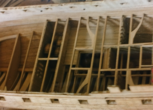
From this point, the process was pretty much a repeat. For each deck, I had installed the clamps to hold the main beams on both sides after putting the ceiling on one side. Then the I did breasthooks and stern hook, then the main beams, heavier for the gun deck, of course, then carlings then knees, both the lodging knees and the hanging knees, and last the purlins. I built the coaming for hatches and installed the various equipment for each deck - the riding bitts, the bitts for the pin rails, capstan, and so forth during this process for the berth and gun decks. I also built the Brody stove and the cannon for later installation on gun deck and spar deck. The cannon are turned from ebony and the carriages are maple. Subsequently, I got a good supply of lignum vitae and began to use it for turning cannon and pully sheaves as well as deadeyes. Lignum is a vastly superior wood for turning and, if you can find the real stuff, get some. You will be very happy with how it works up. The capstans were fabricated from walnut and cherry and maple.
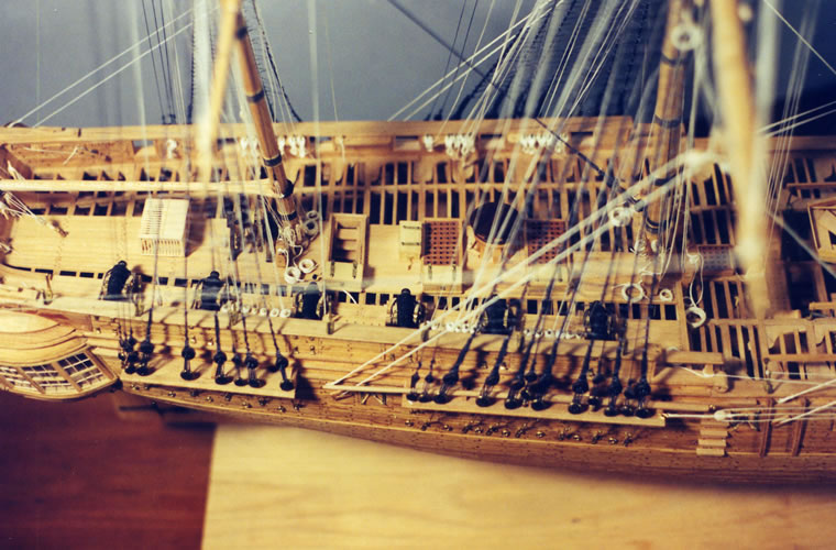
Once the gun deck was timber-framed and half-planked, I finished off the gun ports. On one side, I put in gun port lids and left the other side without. I installed the cannon on the gun deck side with the port lids, in stowed position, run in and secured. I modeled the ship with twelve-pounder long guns, as I suscribe to the idea that she was initially armed that way, with six-pounders on the quarter deck and forecastle. Also, I partitioned off the captain's cabin and the day room, since these will be covered by the quarter deck when it is installed. I also built in sheaves for the tiller ropes and rigged the ropes to the steering quadrant of the tiller and passed them up through the deck timbers to be taken on to the quarter deck and the wheel later.
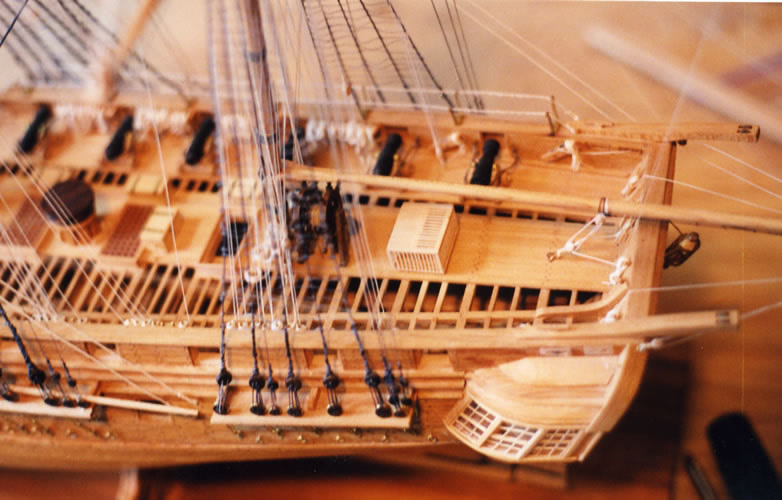
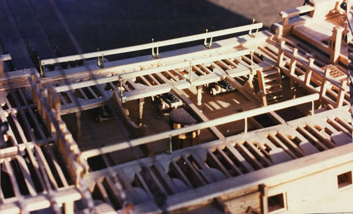
Once the gun deck was pretty much completed, I timbered for the quarter deck and the forecastle and the gangways in the waist. Around this time also I finished off the various railings, adding hammock irons, stanchions and so forth. I also installed the deadeyes for the later rigging. I turned the deadeyes of lignum vitae, which I also used for some of the pulley sheaves in the catheads and bitts. Other sheaves were turned from ebony, which is a great deal less satisfactory, as it is a brittle wood, and chips easily. Lignum vitae turns well and has a natural oil, which lets it polish up nicely after sanding with fine emery paper. I also installed the bowsprit and its bitts before final timbering of the forecastle and did a little detail work on the interior cabins and partitions under the future quarter deck.
I decided to leave the forecastle and the gangways un-planked and to only partially plank the quarterdeck to better show the detail of the interior framing.
Rigging the Essex
I decided to rig the Essex model showing pretty much all the standing rigging and running lines such a ship might have had. This meant adding studding sail booms and hardware to the fore and main yards, (mainsail, topsail, t'gallant yards) and also adding the blocks for sail handling lines including buntlines, leechlines, reefing tackle and the like. I also modeled the mast-head pendants for lifting tackle (Burton Pendants) of the masts, the tackles of the main-stay, and the lifting tackle on the yards.
The first step in rigging the model was to make up the cordage for the rigging. After figuring out what size of lines I needed, I made up a chart. For this model, I decided to use linen for the rigging, which was, in retrospect, a poor decision. Linen is a fragile fiber and will break if bent sharply. So lines tied to eyebolts, for example, may break off at the bolt or at the knot. Also, linen is very reactive to moisture, but gets tighter when wet, looser when dry. The difference in tension of the lines is quite noticible when the humidity changes, and this changing tension makes the tendency to fracture at pinch points even worse. But that was a lesson learned later. I began the process by making up samples for the various lines.
I made the lines up using my rope machine. See the "Ship Modeling in General page for more detail on how I make up rope and cable, and for calculations of the various sizes of line needed. The example used in that section is based on the rigging of the Vandalia, but the calculations for sizes are pretty much universal. The information there is also based on my experiences with cotton, a much better choice of fibre to use for modeling. I have only used "natural" fibres in my rigging - 100% cotton is so far my standard, but I suspect that many of the newer man-made fibres would be as good, maybe better, and last just as long.
I began with the standing rigging, which, after I spun it up, was dyed with leather dye to look "tarred". In general, I rigged the model from stem to stern, rigging first the bow sprit and the lower masts, then I installed top masts and rigged again from stem to stern, working the jib boom and top masts, and so forth.
Here are some photos of the model as I set up the running rigging. Notice that on this model I included the ring-bolts for preventer shrouds.
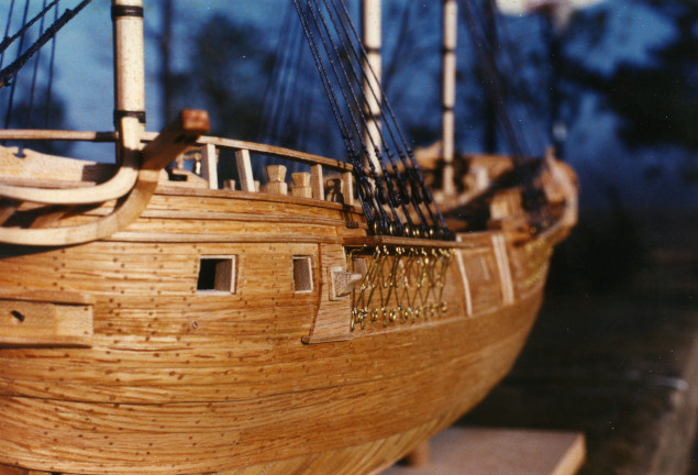
Detail of the foremast shrouds, showing ring bolts for preventer shrouds.
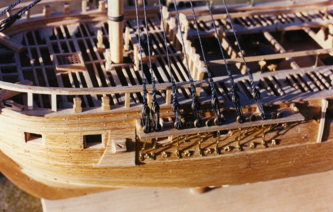
These pictures show the set up of the shrouds for the fore and main masts. Note that I am rigging the lower masts without the topmasts in place, just as the original would have been rigged. Once the lower masts are all rigged I add the top masts and rig them. The last picture in this series shows the mizzen shrouds being rigged.
Final Rigging of Essex
This series of pictures shows the model after the running rigging is done. Along with a few intermediate shots in process.
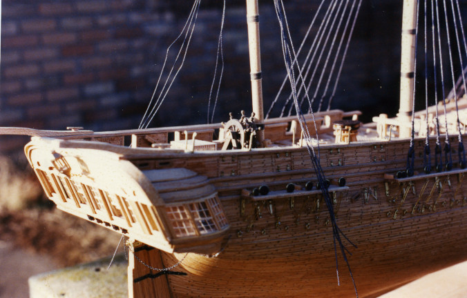
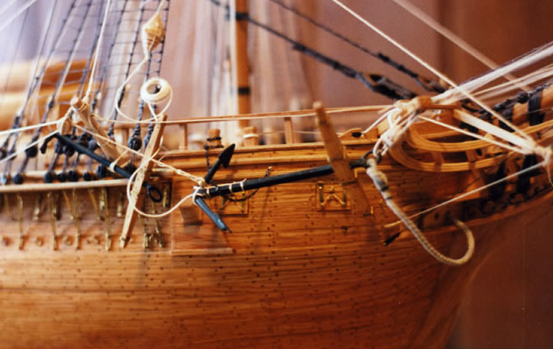
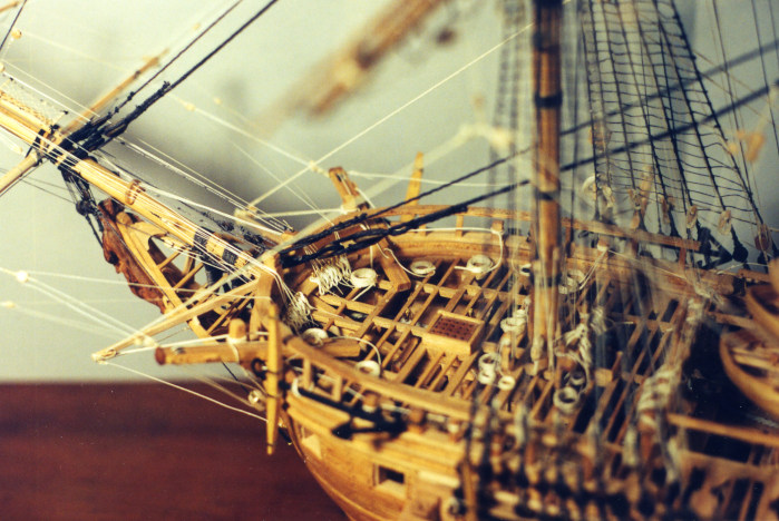
On the portside, ,the anchors are stowed. One is lashed to the fore chains, the more forward on secured to the gunwhales. The heavy block of the cathead lifting tackle is secured to an eyebolt on the hull. The anchor buoy is stowed on the fore shrouds.
The starboard best bower anchor was shown "fished" and "catted", that is, out of the water, still connected to its cable, held on the hook of the cathead block, and secured to the cathead by a lashing, but also held by the fish tackle. There is a fish davit rigged on that side with the hook of the fishing line on the shank of the anchor and the other end stropped to a large viol block, which makes up the hauling tackle for the fish. The hauling end of the fish tackle block belay leads inboard abaft the waist. The anchor buoy is still attached to the anchor, the buoy line led aloft and the buoy stowed on the fore shrouds. The fish davit and its associated tackle was used to raise the flukes of the anchor without allowing it to contact and damage the hull. Once the anchor flukes are raised, the anchor is secured to the gunwhales or additional tacke is used to move it back to the fore channels.
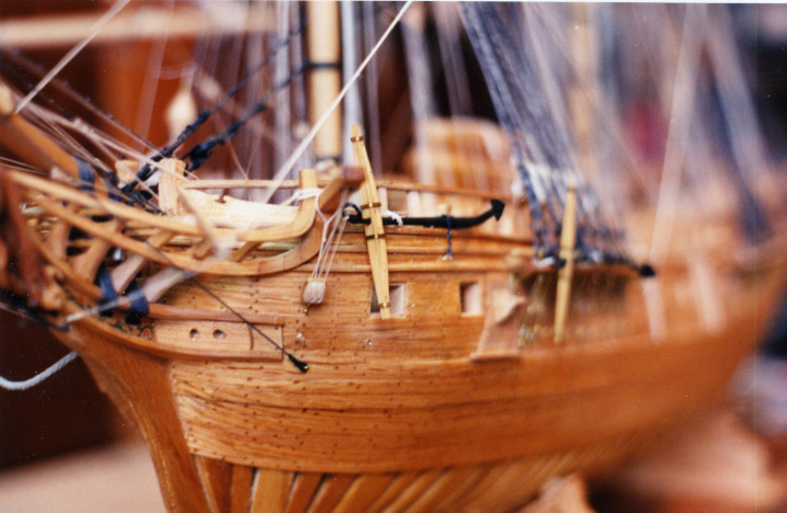
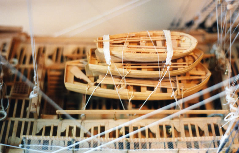
The first few show the bows with the anchors as described above. The ships boats are carved from solid wood and detailed with fine wood and cardstock then painted. They stow on cradles on the timbers of the spardeck in the waist.
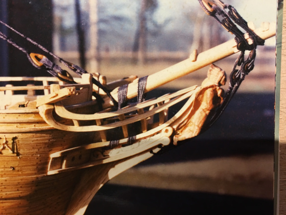
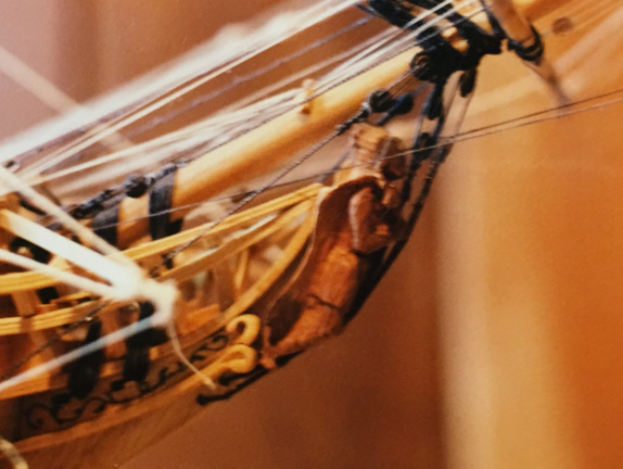
Pictures below show the figurehead before and after adding the running rigging>
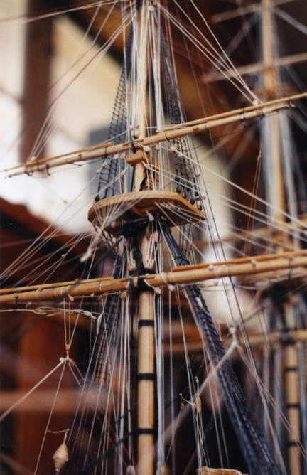
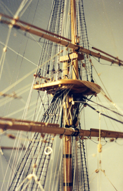
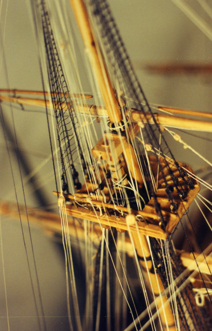
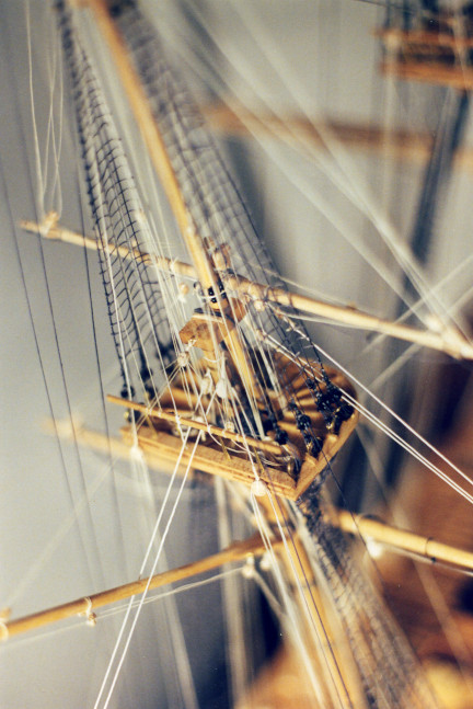
Below are pictures of the fore mast top and the main mast top to show the studding sail booms and the sail handling lines (buntline, leechline) and the lifting tackle on the mainstay. Leechlines and buntlines are attached to cringles on the edges of the sail and lead up to blocks on the yardarm, thence to blocks on the foreward edge of the top, then to blocks on the after edge of the top, then down to belay on the pin rail. Since the mizzen lacks a course, it also lacks these lines. Last is a photo of the mizzen top.
The following pictures are of the finished model. Starting in the waist, and moving
back to the quarter deck.
In these shots of the finished quarter deck you can see some of the additional
detail added including several boxes for small-arms storage and even the chicken
coop, abaft the wheel.
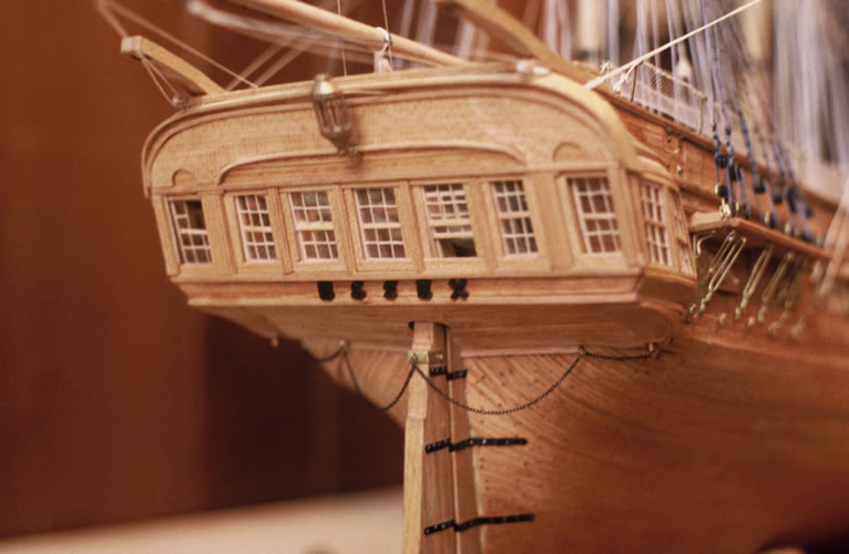
The transom, when completed. Actually, only nearly completed, as I damaged one of
the sashes in the portmost transom window and had to replace it before calling it
a wrap. So it goes.
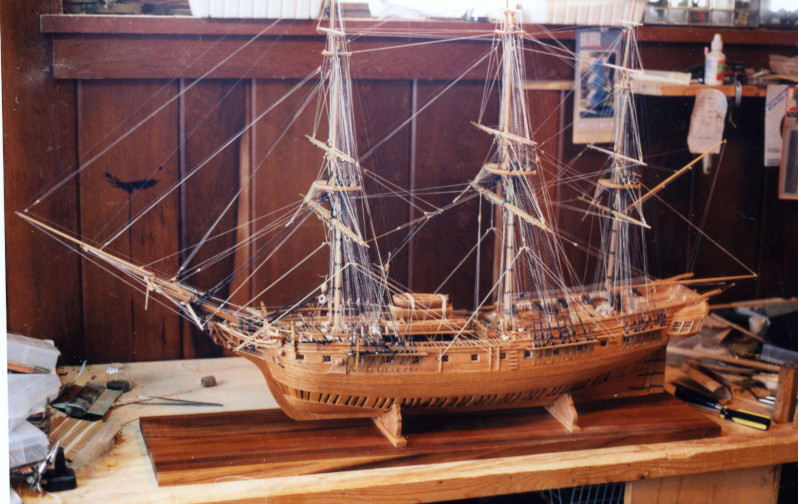
And here is a last shot of the model in the final stages of rigging on the work
bench. This was taken in Ardmore, OK, in about 1998.